We use cookies to personalise content and ads, to provide social media features and to analyse our traffic. We also share information about your use of our site with our social media, advertising and analytics partners who may combine it with other information that you’ve provided to them or that they’ve collected from your use of their services. You consent to our cookies if you continue to use our website. Term of use & Privacy Policy

Products

GP Rail #01

European Rail Traffic Management System: Driver Machine Interface (DMI)

Before the change

In the UK rail industry, the ERTMS system is being deployed When ERTMS is being integrated within the UK, the ERTMS will display the pre-existing safety systems on the DMI. It is really important for the driver to see the faults and failures of the DMI. We were not designing ERTMS but rather designing the Driver Machine Interface (DMI). It was important that this project considered the human in the system when designing the DMI.

Previously this may have been neglected on other elements of the DMI. We considered things like a flashing indication and not considering that it could be distractive, or the sequence of the buttons that were not appropriate to the hierarchy of the decisions that would be made by the driver.

In conventional signalling, the driver will observe outside of the train cab to a visual signal (red, yellow and green) but you can imagine that based on the limitations of the human performance this is not a perfect task. If the driver had a lapse they may pass the red signal and thus ERTMS prevents this as the driver can anticipate the next place to stop at the movement authority and the system controls braking.

N.B. It is not possible to provide a single picture that accurately illustrates the DMI before, as all the indications that were changed are never visible at once. Rather we will focus on a single screenshot of one of the scenarios that resulted in a change of one feature on the DMI. The description of how this feature changed can be found in the next section.

After the change

By considering the driver, it meant that we could implement and integrate our findings into the rail industry standards for the UK. So then when equipment designers want to know how to design their DMI they can access the HF recommendations that we made and integrate them into their design. These recommendations were directed only towards the DMI design.

In the future we imagine that there will not be any signals on a physical post but rather the MA will be communicated through the DMI.

It is important to note that there is only a small number of trains use ERTMS because of costs and challenges with implementing it. The standards speak for themselves and the information is accessible for the designer to integrate it into future projects. It is up to the designer to consider the standards and I hope it will be used in future designs.

The initial touchscreen DMI design presented to drivers included the ability to reinstate the TPWS via the DMI by pressing the yellow button labelled ‘TPWS Isolated’. This button appears once the system has been isolated using the external switch, however it was not intuitive for users that TPWS could be reinstated. This was because the yellow square labelled TPWS isolated was acting as an indicator informing the driver that the system was isolated but also as a button that functions in re-instating the TPWS. As such the label of the indicator did not match the function that the button carried out. Therefore, following feedback from users, it was determined that an additional white button should be added, labelled ‘TPWS Re-instate’. End users were given a choice of text labels including ‘TPWS Switch on’, ‘TPWS Restore’ and ‘TPWS Turn on’. ‘TPWS Re-instate’ was the most popular option and is consistent with the terminology used in the railway currently.

How and Why

We needed a standardized approach for showing the symbols and the buttons on the DMI, and so we took a HF approach to this project. We ran usability trials with 20 drivers and we showed the drivers on a simulator the different designs that could appear and asked their opinion to understand if what we had designed was intuitive. This was fairly early on in the design process.

At the beginning of each usability trial, participants were briefed about ERTMS, the equipment to be used (see picture) and completed a familiarization drive. This enabled participants to get used to the route and the simulator display and controls. Drivers were also asked to use the ‘thinking aloud’ method (Lewis and Mack, 1982) . The ‘think aloud’ process was explained to drivers using a demonstration video showing a user navigating a website and voicing their thoughts, expectations and difficulties. A non-rail example video created by Nielsen (2014) was used to avoid influencing the participants’ responses to the operational scenarios that would follow. Participants were asked to use the think-aloud process when operating the DMI. They were asked to speak aloud their thoughts on: what they were seeing, how they interpret the display, their view of the system status, how they expect the DMI to behave and any frustrations they experienced.

Participants ran through 10 operational scenarios throughout the trial. Two human factors researchers were present for each trial. During each scenario, the researchers would observe the participant’s interactions with the DMI. Comments made by the drivers using the ‘think aloud’ technique were recorded and there was some discussion with drivers about their views and actions at the end of each scenario. Questions and topics discussed were informed by relevant usability heuristics (Nielsen, 1994) such as; ensuring visibility of the system status, error prevention and helping users recognize, diagnose and recover from errors. In addition, a small camera was positioned on the desk to record drivers’ interactions with the DMI. This ensured that any incorrect interactions or attempted actions were also captured. The driver inputs to the simulator were also recorded by the system and stored after each scenario.

At the end of the trial, participants completed an adapted system usability scale questionnaire (Brooke, 1996). This was to assess the usability of the existing safety system controls and indications.

We then took on the driver’s feedback and redesigned the DMI to take into consideration the issues raised. We ran the findings past the equipment suppliers (the train hardware designers) to ensure that our suggestions were feasible. This included the colour of the indications that appeared on the touch screen DMI, the size of the buttons, the parameters of the buttons (flash, steady). It was not entirely a perfect process because what we could design was constricted on the functionality of the DMI. Some of our initial ideas in an ideal world would have been more usable and intuitive – but because the system had already been designed, it meant that we were limited in what we could actually do. The key was the design of the DMI and not of the whole system.

This HF intervention originally for the Rail sector is transferable between Aviation and Maritime, as pilots already use Visual display units so some of the principles of design we considered may be transferable, however, we must remember how constrained we were based on the original design. Aviation and Maritime may be ahead of the rail or have other systems already in place that are more compatible with HF design recommendations. This intervention impacted the UK Rail Industry Standards for DMI design. This like most DMI changes are post design and thus reactive and hence occurs between the design and the development stage. It required a medium to high effort as the analysis took a long time given the qualitative feedback from the drivers. In terms of supporting tools, we needed the simulator for the drivers to use and then we used the systems usability scale questionnaire (SUS) to test if our design was usable or not. The final output included a report with recommendations that fed into the Rail Industry Standards.

GP Maritime #02

Global transversal ship verifications- flows analysis example

Before the change

CETENA was hired to conduct the HF assessment of a ship design that the Client was carrying out. Unfortunately when the activity started the Client had already completed the basic design phase and could not substantially modify it despite the suggestions made. In fact, their ship had some flaws from an ergonomic perspective.

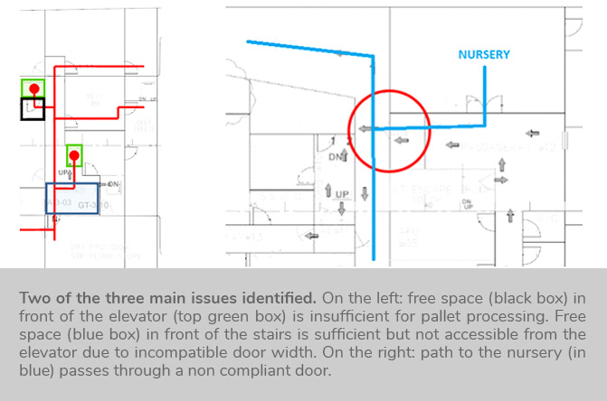
Three main issues were identified:

1)In front of the food stores, there was no free area for the transpallet to turn, so the operator could easily get stuck and he had no place for dismantling the pallet before fitting provisions in the stores. Moreover, the width of the elevator door was exactly the same as the width of the transpallet used to fetch the provisions, another aspect leading to potentially serious problems due to the missing clearance.

2)Analysing the path from the top deck to the nursery, it was pointed out that the path had a very big flaw, i.e. a very sharp bend between two corridors that made it very difficult for people carrying a stretcher to make the sharp turn. The difficulties are due to the stretcher’s length and the fact that carrying an injured person greatly limits the movement the stretcher can have. For completing the transportation, the patient has to be lifted at weird angles in order for the stretcher to make the turn.

3)The location of the lifts for ammunition stores was analysed. Ammo pallets are delivered on the top deck by a crane and then a lift is required to take the pallets to the ammunitions stores. If the lift doesn’t work then the ammunitions boxes need to be taken to the stores by hand, dismantling the pallets on the top deck itself. The ship had a really long way to reach the ammunitions stores that made it impossible to complete the operation by hand in a short time and without excessive fatigue to the operators, due to the fact that the Client did not properly take into account guidelines on hand transportation, leaving it to operative crew members on-board. This aspect is quite typical when evaluating designs carried out by shipyards of emergent economies, where society stratification is more pronounced and the greatest part of the attention is on Officers comfort, while lower ranks are usually less considered.

After the change

The aforementioned issues were pointed out paying attention to include indications on how to improve them.

1) Free area in front of the food stores: it was simply suggested to increase the available area and to enlarge the lift door.

2) Sharp bend between two corridors in the path to the nursery: it was suggested to increase the corridor opening to ease the manoeuver when carrying the stretcher. A specific habitability guideline exists on this issue in Fincantieri guidelines database: [Hab. 3.136]

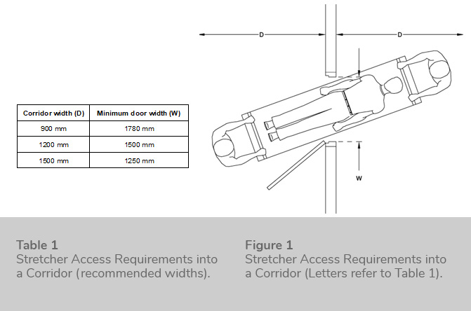
The minimum door width for access with a stretcher directly into a corridor at right angles to the door depends upon the width of that corridor. Table 1 and Figure 1 show the door width required to move into different widths of corridor without unduly tipping a stretcher.

Location of the lifts leading to ammunition stores: the Client understood the flaw but there was no way to solve it and accepted the operativity reduction counting on the massive available workforce on-board to complete the ammunitions loading operation in a finite time.

Overall, it is unknown whether the Client did any changes based on the analysis. However, they learned the process for integrating HF requirements at design phase and understood the implications of overlooking HF aspects and trying to solve them in a more advanced phase. Moreover, the consequences of developing a ship design that satisfies higher ranks needs despite a decrease of comfort for lower ranks was pointed out, and used as the main argument for explaining the inefficiencies and the lack of effectiveness of the design.

How and Why

This methodology is normally applied in Fincantieri Group and goes by the name of Flow Analysis, an effective tool for evaluating the design of a ship from a general perspective. A ship is a very complex environment, where hundreds of people interact and carry out possibly conflicting activities. The majority of physical-related activities involve movement (e.g. moving from one compartment to the other to perform maintenance, carrying materials with transportation tools, queuing for lunch, reaching the area of operations for safety reasons, etc), an activity onto which the topology of the ship and the placement of compartments has a huge impact. The usual procedure for such a study requires looking at the general arrangement while defining a block diagram that follows closely the movement of goods or people. Then, for each block the HF expert has to detail basic questions like what, when, who, where. In this simple way knowledge is gained on how the designer intends to plan the activity and critical steps are easily identified. A strong knowledge of best practices, international standards and generally speaking experience on the field is absolutely mandatory, since the ergonomist must warn the designer on the overlooked aspects and motivate the importance of the identified gaps.

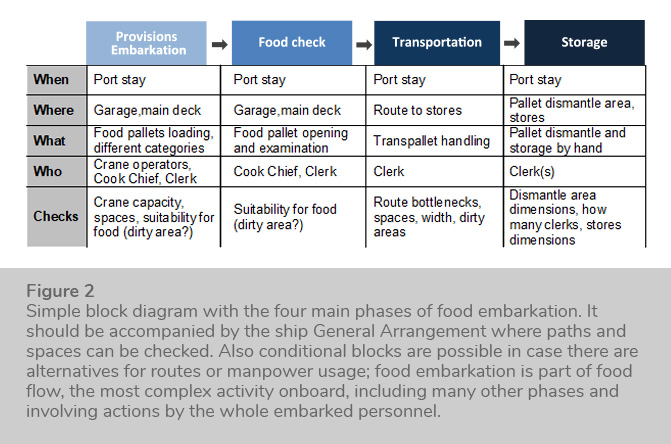
Usually these activities are done for a variety of ‘flows’, including

-Food flow (provisions embarkation, preparation, consumption, waste disposal, etc)

-Ammunitions handling, from main deck to ammunitions stores including weapons refilling activities

-Safety teams operations, where it is demonstrated that safety teams can access every part of the ship while wearing bulky protective clothes

-Evacuation routes with a qualitative evaluation of bottlenecks (to be refined with an actual software based evacuation study if requested)

-Injured personnel recovery (access to nursery, bottlenecks free paths)

The flows also depend on the kind of ship operation and may include CAD verifications for fine aspects (e.g. manoeuver spaces for a fork lift inside a store can be checked geometrically). This HF assessment can be done at any stage of the design/build process of the ship but it can result in actual improvements only if it is performed during the basic design phase. If done in other phases, most probably the suggestions will not be followed due to the many constraints on ship compartments dimensioning and positioning.

GP Rail #02

The train protection and warning system (TPWS)

Before the change

The aim of the system is to stop a train when the driver passes a red light (a signal of danger). A critical incident occurs when the driver passes this signal and the TPWS ensures that the train brakes are applied automatically. However, the system was also designed to apply the train’s brakes in some cases when the driver was going too fast, so a driver would be driving on an open line and if they were going over the speed limit then the brakes would be applied and the train would come to a stand. Therefore, there was a dual function.

Unfortunately, the visual warning in the train cab (what the driver sees as an indication, a red flashing light with the label ‘brake demand’) was the same for both of these situations. If they were speeding or if they passed a signal at danger they would receive the same brake demand light. The basic problem was that the system did not differentiate between speeding and passing the signal at danger. In both cases, the brakes were automatically applied. Across the network, drivers were experiencing an over speed signal more frequently, because you only need to go over the line speed by a little to activate the alarm. When you have an over speed you were permitted to restart your train and carry on, but if you went past the signal at danger, it required communication with the signaler prior to moving the train. So, a driver would experience the brake demand, see the red flashing light and then assume that they had an over speed when in fact it was because they had passed the signal at danger. Therefore, the drivers were resetting the cabs themselves without talking to the signaler following a signal passed at danger, which creates a risk.

For the non-optimal initial design, if you went past a red signal, there would have been a red signal outside of the cab and drivers are trained to drive to the signals. If they over speed it is likely not be in the location of these signals. So when designing the system, designers did not take into consideration that a driver might be unaware they had passed a red signal or confuse this event for an overspeed. The driver would have had an audible alert to inform him that they are approaching a red signal and would then see a red light, most often head height, outside of the cab, so this approach assumes that drivers will see the signal. This does not take into account the fact that drivers may be distracted or that they might see the signal and misperceive it despite their training. If they are used to thinking the alarm occurs when they are going too fast, then they will assume the in-cab indication is due to speed and not due to passing a red signal.

After the change

The design solution that has become part of design standards is for there to be distinct visual warnings to the driver for both when they have passed a signal at danger and when they are driving too fast.

This was the simple solution but in order to gather data for the requirements simulation trials were undertaken. The original non-optimal system with a single light was already in operation and a simulation was undertaken where drivers were presented with over speed scenarios and signal passed at danger scenarios with the existing and options for the new interfaces. In the new design, voice alarms were also added, for example stating “Signal past at danger”. So rather than an audible tone there is a recorded message to further disambiguate whether the red light is due to speeding or passing a red danger signal.

How and Why

As part of the design, we could compare and demonstrate the improved human reliability with the improved display. We also used Human Reliability Assessment in the context of a multi-disciplinary team of engineers, suppliers and HF specialists. The human reliability assessment process was based on task analysis, error analysis and quantification using human reliability data from HEART, following the procedures presented in Kirwan’s A Guide to Practical Human Reliability Assessment. The design process involved TPWS panel manufacturers who could quantify the costs of different design options.

Going through the process, reduced risk and made it safer because we had fewer cases of the drivers resetting and continuing after a signal being passed at danger, when they should have instead communicated with the signaler.

This HF intervention originally in the rail sector is transferable to the aviation sector as there is a lot of simulation in air traffic control. The intervention produced changes to the Industry Standards for the design of the TPWS Display. It also imposed the HF principles of an un-ambiguous alarm system, and promoted the process of user trials and human reliability assessment (HRA) because the change would mean a significant cost to the industry which is why a strong justification for the change was needed. The safety approach was reactive, as we reacted to a non-optimal design and then created a new one. The manpower to resource the simulations took 3-4 weeks with 20 train drivers and 2 HF Specialists. We also required a train simulator. Following the HF intervention, and hence the changes to operational standards, companies are required to use the new interface for new train cabs. Training of staff and updates to procedures were also undertaken.

GP Aviation #03

Design of an HMI for the PTZ cameras at the Remote Tower Facility

Before the change

HungaroControl has a contingency site for its tower operations that is remotely located from the airport. The visual representation of the airport is provided by a video system. As part of the visualization, there are a number of PTZ (pan-tilt-zoom) cameras installed. These cameras are zommable and maneuverable remotely, therefore they substitute a binocular for air traffic controllers. At the original indstallation of the visual system, the HMI to monitor and control these PTZ cameras was a simple HMI on a separate screen (see image below). It showed simultaneously all of the pictures taken from different viewpoints covering different areas, and below that, we had preset buttons that are shortcuts to “frequently viewed areas”.

During the validation process, we found out that this setup does not support the spatial orientation of the ATCOs, because each PTZ camera showed a different part of the aerodrome and it made the identification of the origins very difficult. The maneuvering of the cameras was also challenging only with a mouse.

After the change

After understanding the issue with the original design (setup does not support orientation and manoeuvering), on the impoved HMI we display the orientation of the PTZ cameras on a simple airport map.

Now on the PTZ control screen, you can see a map and you can easily identify which PTZ serves your purpose, which one to choose to observe a certain area. Then by clicking on the area on the map, the PTZ turns automatically in the right direction that you want to visualize.

It is much easier to interpret the picture, the time it takes to manage the system decreased, so it is easier for the ATCO to use. In general, it contributes to maintaining situational awareness by supporting quick information collection.

How and Why

When installing the first version of the video system, we went through a full cycle of design, implementation, testing, and validation and this particular issue arose during the first cycle of validation. So after that, we went back to design and validation and as a result, this new function was created. In case of the contingency tower, the testing and validation is done during shadow operations. The HF experts are there making observations, creating surveys that the ATCOs can fill out. The HF experts also take part in debriefing sessions and facilitate other discussions after the sessions, which are used to define recommendations and requirements that are in line with the ATCOs capabilities and expectations.

The validation exercizes are normally concluded in a long list of recommendations, in this case the need to improve on this HMI function was only one item on that list. Similarly, the scope of improvement changes was borader than the fixing the HMI.

During the project we used a methodology based on EUROCONTROL’s Human Factors Case that is exceptionally valuable to systematically assess and mitigate the risks associated with human factors aspect of a change. It also can be used to realize potential benefits that might be outcome of the change. In this method, the assessment runs parallel with the change project assuring that HF perspective is applied during concept, design and validation phases. In our case, during the HF process, validation needs were identified for the PTZ functionality, then the result of the validation did not met the pre-defined acceptance criteria, hence a corrective action was taken.

Human factors interventions of this kind are not supposed to be isolated actions to improve the operations or a system. Their goal is rather to facilitate a discussion and involvement of the air traffic controllers (our end users), the ATM experts, the technical experts, safety specialists, human factors analysts and the project manager. At the end of the validation cycle, the team jointly comes up with recommendations and requirements, so the key to success is basically the team effort, clear communication and continuous involvement. In the case of refining our Remote tower facility, the value of having a very good team can not be overstated. Safety experts, ATM experts, HF experts and the technical team (e.g. system engineers, designers) could all bring their knowledge to the table and by that navigating the design process to a satisfying outcome.

N.B. Safety assessment and human factors assessment at HungaroControl are integrated, therefore the list of recommendatins include both safety and HF interventions.

This HF Intervention is possibly transferable to the maritime sector, however, the standards are specific to aviation and hence not necessarily applicable to other sectors. The intervention used Risk informed design and hence a proactive safety approach during the design and development stage. It required an advance level of HF expertise due to the number of experts that contributed to the HF intervention. A medium effort was required during the course of 6 months during which other functionalities were also simultaneously developed.

GP Aviation #04

Operations Design of Optimizing Airspace

Before the change

At Hungaro-Control, we run airspace structure optimization projects to ensure efficiency whilst taking into consideration safety and human factors as well.

In our most recent airspace design process, there was a concept that failed to gain acceptance among the Air Traffic Controllers. This was the result of a simulation that showed excessive workload and decreased situational awareness.

After the change

The validation team provided recommendations that lead to a new airspace design to account for the increased traffic and at the same time can support the Air Traffic Controllers' capabilities.

It ensured that the process was thorough and well thought out. Our intention was to make all the potentially affected human performance areas prior to the validation explicit by interviewing our end-users. I think that even if the HF experts had not been present in the simulation, the ATCOs would have still indicated to the management that there were issues. It’s not like we have intervened- we were there to observe, to initiate discussions and essentially to put everything that was said and witnessed into the HF context.

Human factors interventions in my mind is not an isolated action to improve the operations or the system. It rather facilitates the continuous involvement of the air traffic controllers (our end users), the ATM experts, the technical experts, safety specialists, human factors analysts and the project manager. At the end of the validations, we jointly come up with recommendations and requirements – the key to success is basically the team effort, clear communication and continuous involvement.

How and Why

On how the HF recommendation was produced:

When the design such as the one described is made, we will test it and validate it with a simulation. The HF experts are there making observations, creating surveys that the ATCO can fill out, and we also take part in debriefing and discussion sessions and facilitate other discussions after the simulations, which will enable the opportunity to define the recommendations and the requirements that are in line with the ATCOs capabilities. In this particular situation, we choose not to use standardized questionnaires but rather questions targeted at this particular operation. We interviewed the affected ATM actors about their concerns and the potential benefits of the concept, but most of those could only be validated in a human-in-the-loop simulation. So we were present during the simulation sessions and the discussions, made observations, went directly to ATCOs if we had a question, analyzed the results of the questionnaires (which was put together by the project team) and then described the evidence detailing why it was not recommended to implement the new concept. The outcome was presented to the entire HugaroControl TEAM of experts (i.e. ATM, ATSEP, safety experts). In the case of Airspace Optimisation, the value of having a very good team with safety experts, ATM experts, and the technical team (e.g. system engineers, designers) team means that everyone brings to the table their knowledge in their particular fields. The same method was followed afterwards, in the new validation cycle.

This HF intervention is potentially a proactive safety transferable between Aviation, Maritime and other Sectors. It led to a risk-informed design, as this design of the airspace that was put into place before the operations. It also used an approach that was implemented during the design phase of the application. The project required an advance level of HF Expertise as it required familiarity with the ATM domain and took 6months to 1 year to complete. No supporting tools were required, however, we have worked in accordance with the SOAM - EuroControl Human Factors Case Methodology, in addition to working with HungaroControl’s methodology.

On why the HF recommendation was successful:

The final output of the HF intervention is an airspace design validated to support ATCO capabilities as it does not impose unacceptable communication or workload efforts. This ensures that the resultant changes do not make an additional burden to the communication and workload. The operational documents have all been updated with the new design.

GP Aviation #06

Support to perform the rotation with the right input during take-off – HMI

Before the change

We participate in a project that ends up improving the indication for takeoff, meaning providing the pilots and the crew indications on the appropriate rate at which the rotation should take place (i.e. how much the pilot should pull on the sidestick). During takeoff when the pilot reaches the appropriate speed they pull on the side stick and it should not be too much otherwise the tail of the plane will touch the runway and it should not be too little otherwise the plane will not take off.

This new project provides a means to the pilot to guide him or her in administering the correct amount of rotation. Pilots are trained on the correct amount of rotation to apply depending on the aircraft and depending on the takeoff. The HF and Airbus project provides the pilots with the support they need for a smooth takeoff. It was not an HF pushed project but rather an airbus project that incorporated HF.

After the change

The preliminary design was modified from an HMI point of view and some procedures and guidelines were produced so the pilot could understand what the new HMI is for, and how to operate it. The Airbus test pilots approved and accepted the new design during the simulations. These pilots play a large role in the design as they are our end-user during the simulations. The airbus pilot community represents the end-user for us so we design for them. If they are not happy and if they do not accept the design, then they have the power to stop a design solution or to steer the design. Their role is justified from my point of view because they know the operation, the risks and they know what the work of a pilot is about.

There is a feedback system with regards to new designs, but we are not directly informed on how the airline pilots perceive the new designs but I would say that if there were major complaints we would know. If the clients were not happy it would have triggered a re-design or a modification and then that would have been shared with the engineers and the people that are working with the document. At my level, no news is good news. But I am sure that people in other parts of the organization have a much clearer understanding of the pilot’s perception of new designs and solutions.

The output of this process is a new design and the documentation to certify the solution for the regulator. The certification body EASA approved and certified the solution if they think it is acceptable from their point. This was the case and this new design has been implemented in the A350.

How and Why

On how the HF recommendation was produced:

First, the engineering part develops an ideal solution and this is discussed in several meetings where the different specialists, including HF, participate to bring different points of view on the table and to develop and mature the solution up to a point where that solution is evaluated. In the evaluations process, we as an HF specialist have the responsibility to define evaluation’s HF objectives (that are collected in a “table of objectives”) where we list what we want to assess in the evaluation, what we want to test in the simulation, and what risks of error we are concerned with. The evolution takes place in either simulators or real test flight, in both cases we define the scenarios where we consider that the risk of an error is possible, in which pilots are subject to workload, where situational awareness is potentially affected etc. So we expose the design solution to several airbus tests and training pilots and we observe and debrief with the pilots on the understanding of the behaviour of the new function that we are developing/improving. So out of this evaluation campaign, it depends on the new solution, but you may have several simulations. The bigger the new solution, the bigger the evaluation campaign. Once the preliminary design was tested, we at the HF team provided some HF recommendations. Linked to the Objectives tables, we saw some errors or some workload issues during the initial trials.

For example, pilots need to monitor 2 things at the same time and so it can cause some workload issues. So we came up with 2 two types recommendations: either recommendations for system design from an HF perspective (e.g. the shape of the indicators on the primary still-display should be modified somehow) or we can push the recommendations to the operational group if we feel that there are HF recommendations that need to be made for the training of the new function. We identify the need for an example of a need for additional training but it is up to them to determine their HF suggestions. All recommendations are discussed in the inter-disciplinary meeting. For example, we could recommend to modify the shape of the display and then the people who are responsible for the displays and have the technical knowledge can then determine if it is feasible or not from an economic, technical, and legal point of view. Regardless of whether the application of recommendation is or is not possible, it needs to be justified. From an HF perspective, we do not always have a clear understanding of all of the constraints that the other stakeholders have and that is why we share the recommendations.

We do not use any form of a formalized method, but we comply with a strict design process that is shared with the regulator. As I said we define what are the HF issues that we are concerned about and our error and workload and situation awareness issues. For each of these topics, we define the subtopics of each of the concerns we face (error manipulating controls, etc.). So we build a very detailed set of items we are concerned about and then we check in the evaluation whether our concerns are valid or not. If the concerns are valid, then we provide recommendations because if we assess that there is the need to improve the design or the system then we issue recommendations. Then the recommendations are discussed and either they are accepted or rejected with justifications in both cases.

On why the recommendation was successful:

It was successful because we were able to point out the need for improving the solution. There is always an issue in negotiating the different constraints that all the different partners have. In this case, the new design solution was sensible, cost-efficient, technologically feasible, from a safety perspective it was important to have this improved solution and therefore the trade-off from a business point of view and a safety point view they acknowledged the interest of improving the design. I think there is never a single factor that makes a recommendation successful or not, depending on the recommendation, on the stakeholders involved, and what we are trying to do.

GP Maritime #01

Bridge re-design intervention to solve glare problems – Single compartments design

Before the change

We received the request to assess specific ergonomics aspects related to a custom shaped bridge for a new ship whose design phase had already been completed. For the Industry it is very common nowadays to receive requests to innovate the bridge compartment layout, mostly because the ‘classic’ design has not changed significantly over the last 50 years, and today’s technologies allow modifying the usual ways to convey information to operators, hence new shapes become possible and new concepts can be explored. In particular aviation-like cockpits (backed up by rear consoles for other non-navigation related functions) are a bridge layout quite looked after in these days. However, steering away from a well-known design exposes designers to the risk to under-evaluate specific aspects that with the previous design were not considered because the design itself eliminated them.

Following the requests by the Customer (Navy), the bridge of a newly built ship was designed with a triangular/diamond shape, having in the front part a cockpit with two seats, two rows of lateral (close to the windows) consoles and others in the middle (for Captain and Helmsman) of the compartment.

The Customer lamented that due to the bridge design (especially considering the big lateral and front windows) many operators would have been affected by a glare problem. The complaint was legitimate, as conventional bridge designs have a different shape that does not allow sunlight to reflect on consoles screens (these are concentrated in the central part of the compartment and windows are small, mostly distributed in the forward looking part of the bridge).

Therefore CETENA, without being previously involved in the support of the design process of this ship, was asked by the Customer to do an assessment for the bridge in order to identify the possible corrections to quantify and solve the glare problem as much as possible.

After the change

Countermeasures were suggested in the forms of lids, curtains and screens for each console or window. The dimension of each screen was determined thanks to the results of the analysis.

The activity raised awareness on the negative effects of glare and was perceived by both the Customer and the Shipyard as a great added value; results were taken quite seriously as the Shipyard used them to build a lid for the cockpit console (the most exposed to direct and reflected sunlight) and to order custom electrically controlled curtains for all windows. The study helped clarifying the possibility of a serious problem and avoiding a dispute between Shipyard and Customer, improving the overall quality of the final product, even if better results may have been obtained if the study had been done in the early design phases, where there is still the possibility to change layouts.

The developed software will be used in all future custom bridges assessment.

How and Why

The chosen approach was custom created for the specific problem, as there are no tools that can do such an analysis ‘out of the box’. The first step was determining the position of the Sun in relation to the ship. The locations where the ship will operate were known (they are an input provided at the beginning of the basic design by the Customer), therefore complete information of the maximum sun height, total daily sunlight hours at solstices and equinoxes was assembled and used to produce the test cases.

Moreover, a rectangular test surface was defined representing the position of each console operator eyes, having as upper height the quota of the eyes of the 95%ile and lower limit the same parameter of the 5%ile, with percentiles values set according to an anthropometric database suitable for the reference population. Moreover, a point was also defined for the 50%ile to allow checks for the average of the reference population. The test surface and average point were defined with the aim to allow geometric checks, both manual and automated.

The analysis of the glare was divided in two phases:

1. Glare due to direct sunlight Direct sunlight determination was done manually, as a simple CAD software is absolutely sufficient to do the required checks. Direct glare was checked on a vertical plane centered on the test surface (operator face), and rotated of 30° until all directions were covered. This allowed determining the maximum and minimum offending sun elevation angles, for each operator and for each direction.

2. Glare due to reflections on screens Reflection glare was much more complicated. The chosen approach required programming a sort of ‘inverse’ ray tracing-like tool in CATIA CAD software that for each operator projected a line from the average eye point to the screen, calculating the reflection and whether it was impacting one of the windows or not. This allowed to create a mapping of the screen areas where sunlight could impact reflecting back to operator eyes, correlated with external sunlight angles. The approach was complicated also by the presence of multiple screens for many consoles and considered the presence of obstacles. The determined ‘glare maps’ were also verified by using a proprietary software that CETENA produced to determine naval ships weapons coverage. The software produced a spherical image of what was visible from a single point and the outcomes of its application on each operator were used to determine the same raytracing-like results.

Finally, the obtained glare maps were crossed with sun height statistics in the four days identified in order to determine the maximum potential daily exposure hours for each operator.

Countermeasures were then suggested in the forms of lids, curtains and screens for each console.

GP Maritime #03

Redesign Of Damage Control (Flooding) Simulator

Before the change

In the Damage Control School of the Hellenic Navy, we manage and operate three different type of Ship Simulators: 1) Firefighting, 2) Evacuation, 3) Flooding. The Flooding simulator is the most recent addition and was constructed with limited resources. Therefore, the initial decision was not to include an isolated control room to observe the training activity. However, after running the first demo courses, we quickly realized that this limitation was very important and should be resolved as soon as possible. The problems that were identified were the following:

  • Both trainers and trainees were in the same place, which affected the quality and the realism of training,
  • We could not escalate the scenarios of flooding the vessel, because then the trainers were the last or the first to evacuate and were mixed with the Emergency Response Teams,
  • We could not measure the Technical and Non-technical Skills.

After the change

After redesigning the simulator, by retrofitting a three-station control room, the training process improved. The following benefits were observed:

  • The instructor could now very easily customize all training scenarios and change the events of the plot in such a way that could create a real, unfriendly and surprising environment. This improved the realism of the training process.
  • It was easier for the assessors to observe all the technical and non-technical skills, such as situation awareness, decision making, communication, teamwork, and leadership.
  • By escalating the scenarios in a more realistic way, the trainers and assessors could create more stress and fatigue to the trainees. Therefore, the human limitations are easier to evaluate.
  • Trainers and assessors can visually observe all the training activity from a safe environment and assess human limitations, such as managing stress and dealing with fatigue.

How and Why

A three-station control was retrofitted to the flooding simulator, which was effectively redesigned. The redesign was based on an approach that was similar to “HF Principles Evidence-Based Review” and “Fatigue Analysis” from the SAFEMODE HF Catalogue. Specifically, the approach included the following steps:

1. Questionnaires and semi-structured interviews with trainees and trainers. The questionnaire that was used for getting feedback was specifically developed for the needs of the assessment and experiment by Hellenic Navy safety experts, doctors and psychologists. The objective was to assess the effectiveness and efficiency of the training. The questionnaires were analyzed using established statistical methods. The feedback from the experienced trainers proved to be particularly useful for the redesign of the simulator.

2. Assessment of the trainees’ behaviour with the Hellenic Navy’s Behavioural Assessment rating scale.

3. Stress/fatigue analysis methods. The participants (both trainers and trainees) wore actigraphs (Garmin Vivosmart HR+) during the training activity and data were recorded from the devices. Training activities were conducted for three consecutive days and we had the chance to observe the effects of fatigue and sleep deprivation for 72 hours. The data gathered from the actigraphs were analyzed using statistical regression techniques. The objective was to determine the level to which the scenarios in the simulator may be escalated.

GP Maritime #04

Pilotage: Incident investigation and follow-up actions, due to vessel’s allision at the port of Dhamra

Before the change

When a vessel is entering a port or sails through restricted waters (i.e. a river) it is either advisable or obligatory to ask the services from a pilot, depending on the Port Authority. A pilot is a person that gets on board the vessel and advises the Master or the Officer On Watch (OOW) (it depends who has the command of the vessel) about the positioning, the direction, and the speed of the vessel. According to the “Bridge Procedures Guide” from the International Chamber of Shipping (ICS), one of the most critical tasks for the safety navigation of each vessel during pilotage periods, is the integration of the pilot in the Bridge Team, providing strong evidence of sound Bridge Resource Management (BRM) / Bridge Team Management (BTM) procedures . A good cooperation between Master and Officer of the Watch (OOW) and the Pilot is essential for carrying out this task safely. Usually the cooperation is smooth, but due to the multinational character of the maritime industry there are several cases where the communication or cooperation is problematic. This is often due to the attitude of either the Pilot or the Master and the limited time of interaction. The incident that initiated the change in the relevant procedure for the shipping company is described briefly below.

The vessel, while proceeding under pilotage to her berth, hit the corner of the pier, resulting in a damage on the hull above the water line on her port side (along the top side tank). The contributing factors were the following:

1. Poor cooperation between Master and Officer of the Watch (OOW) in vessel’s bridge – Pilot (Indian) – Chief Mate and Bosun at the forecastle.

2. Miscommunication: a) The orders from the Pilot to the tug-Masters were in the Indian language, which was not understood by anyone from the personnel of the vessel , b) Lack of adequate cooperation between the bridge of the vessel and Chief Officer at the forecastle (e.g. misinformation regarding vessel’s distance from the pier).

3. Lack of experience in dealing with challenges that may arise during pilotage periods from the Master and Officers onboard.

The system/procedure was following (actually, relaying) information and guidance from 3rd parties on the way that pilotage periods should be managed. Therefore, this incident can be classified as a “systemic failure”, as the established and implemented relevant procedures did not take into account the specific characteristics of vessel’s crew (e.g. skills, experience, understanding of the specific requirements out of the cooperation with Indian pilots, etc.).

After the change

In the wake of the described incident, the relevant systemic procedures were taken under scrutiny. In this regard the following steps were followed:

a.The shipping company, following an incident investigation, drafted lessons learned and used them for improving the established procedures,

b.The shipping company’s Designated Person Ashore (DPA) sent the revised procedures to all the company’s vessels for feedback,

c.Comments were incorporated and the final revised procedure was disseminated to all the vessels of the company,

d.Training material (presentation) on the revised procedures was prepared and sent onboard all the vessels of the company . In addition, this material was sent to the manning agent for the training of newcomers and onboard personnel,

e.Continuous review of the procedures is being conducted with input out of the interaction of Bridge personnel with Pilots following vessels’ call at various ports, worldwide.

The revised procedure addressed the identified contributing factors by describing changes in the way of communication. It included a two-way communication model with reinforcement feedback and establishing predefined technical terminology to overcome miscommunication.

How and Why

None of the listed HF intervention were used, but the situation was treated rather empirically. Therefore, the approach was based mainly on the experience of the DPA and the superintendents of the shipping company.